Advanced Real-Time Digital Simulation Lab
RTDS Lab & Software
- The advanced Real-time simulation Lab has three (3) NOVACOR chassis real-time simulator which can conduct Electromagnetic Transient (EMT) simulation for large-scale power systems with thousands of nodes in small time steps (1-150 μs) in real time, the measurement can be monitored instantaneously, and frequency range is from DC (0) up to 3 kHz which is perfect for power electronics converter simulation.
- Six DELL blades for HPC for co-simulation and hardware and software in the loop.
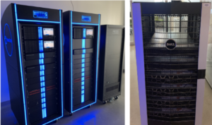
Figure 1: RTDS NOVACOR chassis and six Dell blades.
Research Projects
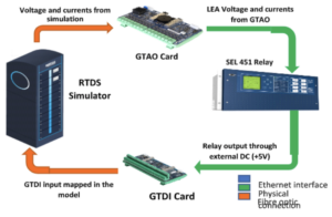
Figure 2a: HiL setup overview.
HiL for Protection:
The transition from big conventional bulk generation to small dispersed renewable electricity production coupled at medium and lower voltage levels resulted in bi-directional power flow and an active distribution network, which was previously considered to be a passive network. This paradigm shift brings many challenges for protection performances and coordination. As a result, this word first investigates the impacts of Distributed Energy Resource (DER) integration on distribution protection and then applies the hardware SEL 451 relay for validation. Two of the most common protection failures with DER integration, namely, reverse power flow and sympathetic tripping cases, are examined for a micro grid in this study.
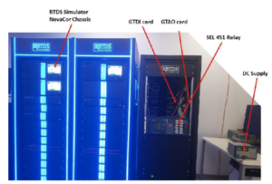
Figure 2: HiL setup in the lab.
Firstly, the system is modeled in Power factory for short circuit calculation and protection coordination study. With the help of PowerFactory simulation, coordinated relay settings are subsequently extracted for validation in hardware in the loop (HiL) testing with SEL 451 relay in RTDS. Both simulation case studies and hardware test have shown that the DER contribution in healthy condition as well as during the fault can result in mal-operation of the relay. Different from the traditional power amplifier-based testing, the hardware in the loop testing in this work uses Low Energy Analog (LEA) signals output from the GTAO card of RTDS feed directly to SEL 451 relay.
Optimal Size and Location of BESS:
BESS can contribute to frequency stability in renewable based systems. However, their successful implementation relies heavily on planning via optimal sizing, location, and operation; as this allows the efficient utilization of transmission capacity and helps adjusting power flow, increase renewable penetration, and reduce power losses.
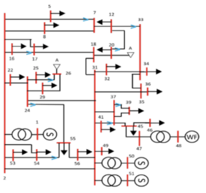
Figure 3: Single line diagram of Sao Vicente system.
In this work, we determine the optimal size and location of a BESS aimed at frequency support to minimize the total investment and operation cost while satisfying power system constraints in the simplified Sao Vicente network. Then, the results are validated in RTDS.
Three scenarios define 10, 35 and 50% of the rated design capacity which are representing off-peak, current and future peak loads. Only one Synchronous generator (SG) at bus 1 is in operation, as those in buses 50 and 51 are re-purposed as synchronous condensers (SCs); while the WF on bus 48 assumes 70% available power as Fig. 3.
Figure 4 shows the BESS’ location-dependent optimal size [MVA] for each scenario. A 1-MW BESS system should be installed in all buses, but 37. Off-the-shelf lithium-ion batteries available in the market can be used in this system. Subsequently, the system is modeled in RTDS in order to validate the optimization results via dynamic simulation. The simulation results for scenario 2 with and without BESS during a 5% homogeneous load step increase is shown in Fig. 3. The system including BESS presents a 36% higher nadir and slower rate of change of frequency: recovering up to 49.95 Hz after 5 seconds. On the other hand, the original system is only able to reach 49.87 Hz. BESS integration ensures higher power reserve capacity available for the SG to react during any eventuality.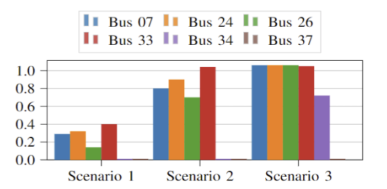
Figure 4: Optimal size and location of BESS per scenario.
Moreover, SC suffer less mechanical stress during inertial response. Overall combining SC’s and BESS significantly enhances the frequency recovery of renewable-based systems.
Dynamic Voltage Support Using Fast Fault Current Injection from Converter:
High penetration of renewable energy sources (RES) into power systems result in challenged system operation and control while the interaction between transmission and distribution becomes more sensitive. This paper investigates the impact of dynamic voltage support provided by fast fault current injection from the converter-based generation present in the transmission system, on a distribution system with a high share of RES during fault conditions. In addition, the impact of a hybrid synchronous condenser and battery system in the transmission network on the distribution system is also analyzed in this paper. The results show that fast fault current injection from converter-based generation and the hybrid system contributes to speedier voltage recovery of the distribution network. Such a faster recovery of the distribution system voltage can prevent the triggering of under-voltage protections for distributed energy resources, thereby increasing the system’s robustness and resilience.
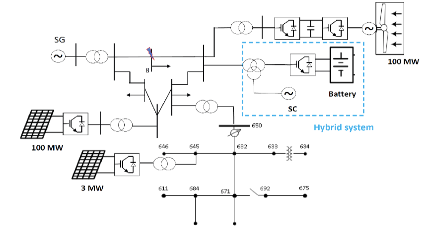
Figure 5: Single line diagram of the transmission-distribution system.
Two different scenarios are examined to verify the benefits of the hybrid system and fast fault current injection during a three-phase short-circuit fault in transmission system. First, a three-phase short circuit fault happened at bus 8 as shown in Fig. 5 of the transmission system is studied to experience how fast fault current injection functionality can help the DER PV in distribution system to survive the post fault disturbance. Then, the role of the hybrid system of synchronous condenser and battery is investigated to determine how it contributes to voltage recovery and thereby assist in keeping the PV synchronized after the fault.
Figure 6 describes the responses of the system, hybrid system and PV generator without (blue) and with FFCI (red) when a three-phase short circuit is happened at t=0.5 seconds and cleared after four cycles. The first two sub-figures show the reactive current injection from wind generator and battery of hybrid system to support voltage during the fault. It can be seen clearly that with FFCI the reactive current is reached around 1.5 pu and 1.25 pu from wind and battery, respectively. Eventually, these fast current injections help the voltage at the PV terminal quickly recover to be within the allowable range of distribution system as shown in the red curve in the last sub-figure of Fig. 6. Without the FFCI case, after the fault, the voltage at the PV terminal cannot recover within the allowable range. Therefore, the PV protection detects an under-voltage violation after 2 seconds and trip the circuit breaker (green curve) to isolate PV from the system, as shown in the last sub-figure of Fig. 6. It is noted that the synchronous condenser can provide inertial support represented via its kinetic energy at approximately 58 MW instead of around 30 MW without FFCI, which helps the system response improve during the fault.
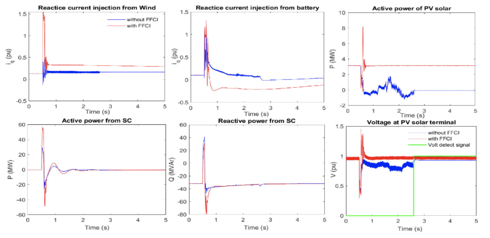
Figure 6: System responses during three-phase short circuit fault with and without FFCI.
Points of Contact
- UConn: Junbo Zhao and Ankur Srivastava